
An FME Workspace Style Guide
“A good looking, well-organized workspace gives the customer the feeling that you have done quality work.”
A good style of design makes it easier to navigate and understand an existing workspace. This is important when workspaces might need to be edited by other users, or when you intend to make edits yourself at a later date.
Specifically, a good style can help a user to…
- Distinctly define different sections or components of a workspace
- Quickly navigate to a specified section or particular transformer
- Pass a workspace on to another user for editing
- Rename workspaces and content with a more explanatory title
In general terms Best Practice means the best way of doing something; in other words, carrying out a task effectively and efficiently.
Despite the word 'best,' we're not presuming the ideas here will meet every need and occasion. One way to define best practice is:
a very good practice to consider in this situation based on past experience and analysis.
In this section we'll talk about a small aspect of best practice - using annotations and bookmarks to make your workspace understandable to others. Both of these methods allow you to document how and why your workspace works as it does. They allow other users - or yourself in the future - to understand what each section does.
Annotating Workspaces
Annotation is a key method for a clear and comprehensible design.
Annotation helps other users understand what is supposed to be happening in the translation and also helps the creator when returning to a workspace after a long interval (take it from me that this is especially important!)
Two different types of annotation can be applied to a workspace.
User Annotation
User annotation is a comment created by the user. It can be connected to a workspace object (transformer or feature type), can be connected to a workspace connection, or can float freely within the workspace.

To create attached user annotation, right-click a workspace object and select Add Annotation, or use the shortcut Ctrl+K when the object is selected.
To create floating user annotation, right-click the canvas and select Insert Annotation, or press Ctrl+K when nothing is selected.
When you place an annotation you have the opportunity to change the font style, font size, and background color; plus you can also add hyperlinks, bullet points, and tables.

Summary Annotation
Summary annotation is an FME-generated comment that provides information about any object within the workspace. This item can be a source or destination feature type, or a transformer.
Summary annotation is always colored blue to distinguish it from other annotation. It's always connected to the item to which it relates and cannot be detached.

The nice thing about Summary Annotation is that it automatically updates in response to changes. That makes it very useful for checking transformer parameters (or reader/writer schemas) at a quick glance. It's particularly useful in situations where the parameters are set through a wizard and are more awkward to check (for example, the SchemaMapper or FMEServerJobSubmitter transformers).

Bookmarks
A bookmark, like its real-world namesake, is a means of putting a marker down for easy access.
With FME the bookmark covers an area of the workspace that is usually carrying out a specific task, so a user can pick it out of a broader set of transformers and move to it with relative ease.
Why use Bookmarks?
Bookmarks play an important role in a well-styled workspace for a number of reasons, including these.
- Design: As a way to subdivide a workspace and manage those sections
- Access: As a marker for quick access to a specific section of a workspace
- Editing: As a means to move groups of transformers at a time
- Performance: As a means to improve workspace performance when caching data.
To add a bookmark, click the Bookmark icon on the toolbar.

Whereas a traditional bookmark marks just a single page in a book, the FME bookmark can cover a wide area of the canvas. A single workspace can be divided into different sections by applying multiple bookmarks.
If any objects on the workspace canvas are selected when a bookmark is created, the bookmark is automatically expanded to include those items.
Resizing and Editing a Bookmark
To resize a bookmark hover over a corner or edge and then drag the cursor to change the bookmark size or shape.

Bookmark Properties
Click the cogwheel icon on a bookmark header to open the bookmark properties dialog:

Here you can change both the name and color of the bookmark and decide about whether contents will move with it (more on that later).
The bookmark colors can be set to an existing color palette or custom colors can be used. Additionally, customized palettes can be created by going to Tools > FME Options... > Appearance:


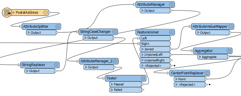
A bookmark is a great way of indicating that a particular section of a workspace is for a particular purpose. By subdividing a workspace in this way, the layout is often a lot easier to follow.
As one user has put it, bookmarks are like paragraphs for your workspace!

The above workspace illustrates how to mark up different sections of a workspace using bookmarks. As you can see, it's permitted to subdivide bookmarks further by nesting one bookmark inside another.
Bookmarks for Quick Access
Bookmarks are listed in the Workbench Navigator window. Each bookmark is depicted as a folder and can be expanded to show its contents. It may include feature types, transformers, or other - nested - bookmarks:

Clicking or double-clicking a bookmark in the Navigator selects that bookmark and brings it into view. So when bookmarks have been used to divide a workspace into sections, they can also be used to navigate between different parts of that workspace.
Bookmark Navigator
Bookmarks can also be navigated on the FME Workbench toolbar using the Bookmark Navigator:

Besides being a way to access bookmarks quickly, the Bookmark Navigator tool can be used to present your workspace. By clicking the arrow button (or pressing the keyboard spacebar), you flip from bookmark to bookmark using animation, in a way that would be very useful when showing the workspace as part of a presentation.
Bookmarks for Performance
When a workspace is run with Data Caching turned on, then features are cached at every transformer. As you can imagine, in larger workspaces this leads to a lot of data being cached, sometimes unnecessarily:

Notice in the above screenshot that every transformer in the Prepare Data for Matching bookmark is being cached.
However, when a bookmark is collapsed, then caching only occurs on the bookmark output objects:
Collapsing a bookmark means it is compressed down to the size of a single transformer, displaying none of the contents except for where data enters or exits the bookmark:
Clicking the icon a second time re-opens the bookmark to its previous size.
This functionality allows large sections of workspace to be rendered in a much smaller area, and only opened up when editing is required.

This feature means that data is cached only for the final transformer in the bookmark, saving considerable time and resources:

Collapsing Bookmarks vs Custom Transformers
It's easy to see collapsing bookmarks as a replacement for custom transformers, especially where the custom transformer was intended only as a means to save space on canvas:
![]()

However, collapsible bookmarks are not such a good replacement where the content is intended to be reused in multiple locations. That's because each custom transformer inherits its behaviour from a master custom transformer definition. Editing the definition updates all the custom transformers.
The same is not true of a collapsed bookmark. There is no master definition and editing the contents of a bookmark does not automatically update the contents in any other bookmarks, even if it was a direct copy.
Additionally, a collapsed bookmark cannot be shared with other users and doesn't have the ability to set published parameters, in the same way that a custom transformer would.
So while a collapsed bookmark can replace some aspects of a custom transformer, it can't fully replace them.
Hidden Connections and Tunnels
The ability to hide connections is especially useful for avoiding overlaps. To hide a connection, right-click on it and choose the option to Hide:

A hidden connection is represented by a 'transmitter' icon, or by a greyed-out dashed line when the object at one end of the connection is selected:

Here the object (transformer or feature type) must be selected for the connection to be visible.
The other available option is "Create Tunnel." This choice creates a hidden connection with the addition of an annotated junction transformer at each end:
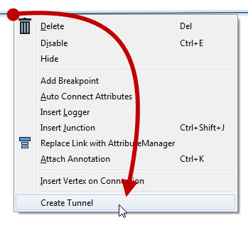
A tunnel is a combination of Junction/Hidden-Connection/Junction!

A tunnel makes a hidden connection slightly more apparent, plus allows for annotation at each end.
Notice that we have a hidden connection, but there is a junction (with annotation) at each end. Now we can move the junctions to manipulate the hidden connection and both the junction and annotation are a much better visual clue as to what is happening.
The space between the Junctions is the hidden portion of the connection. Both Junctions are annotated to indicate the object and port to which they connect across the hidden portion.
So we can choose to either just hide connections or hide them as tunnels with extra junctiony goodness!
Revisualizing Hidden Connections
To view hidden connections, click on an object at either end. The connection is highlighted as a greyed-out dashed line.
To return a connection to view, right-click an object to which it is connected and choose Show Connection(s).


Custom Transformers
Custom Transformers are very powerful tools at either a basic or an advanced level.
What is a Custom Transformer?
A custom transformer is a sequence of standard transformers condensed into a single transformer. Any existing sequence of transformers can be turned into a custom transformer.
![]()
![]()

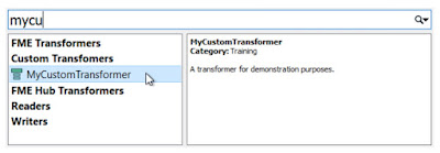
Custom transformers can be shared by users. For example, this MeasureInterpolator custom transformer is shared via the FME Hub.
Custom Transformer Purposes
Among other functions, custom transformers help to:
- Reuse Content
- A sequence of transformers encapsulated in a single object can be reused throughout a workspace and shared with colleagues.
- Employ Advanced Functionality
- Using a Custom Transformer enables additional functionality to be used, such as looping and parallel processing
- Tidy Workspaces
- By condensing chunks of content, the workspace canvas becomes less cluttered
Creating a Custom Transformer
A Custom Transformer can be created from scratch – i.e. you start with an empty custom transformer and add content into it – or can be created from an existing sequence of transformers.
Custom transformers are created by either selecting Create Custom Transformer from the canvas context (right-click) menu or by selecting Transformers > Create Custom Transformer from the menubar. The shortcut key for this function is Ctrl+T.
![]()
![]()

If a number of existing transformers are selected when you issue the Create Custom Transformer command, then they are automatically added to the new custom transformer; otherwise, the new custom transformer is created empty except for an input and output port.
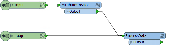
Here a user is creating a new custom transformer based on a series of existing ones:
![]()

The new custom transformer will be pre-populated with these three transformers.
Naming a Custom Transformer
All Custom Transformers require a name and (optionally) a category and description. A dialog in which to define these automatically appears when you create a new custom transformer.
The category can be set to match any existing category of FME transformers or a custom category of your own.
Notice also the “Use Extended Description” parameter. This allows you to enter extra information about the custom transformer, such as requirements for use, development history, and legal terms and conditions; in fields that support the use of either rich text or Markdown.
![]()

These fields are particularly important when you intend to share the custom transformer with work colleagues or clients.
The New Custom Transformer
A newly created custom transformer then looks like this:

Notice that it appears under a new tab on the Workbench canvas and consists of the original transformers with additional input and output objects.![]()
When you click on the Main tab, to return to the main canvas view, the original transformers have now been replaced by a custom transformer object that is automatically connected to the existing workspace:

Editing a Custom Transformer
To edit the contents of a custom transformer, simply click on the tab for that transformer. This opens the transformer definition and you may edit the content in the same way that you would in the main canvas.
In the Navigator window, where a workspace would have a section labeled Workspace Parameters, a custom transformer has Transformer Parameters:
![]()
This is where the information – name, category, description, etc. – that was entered earlier can be edited.

Using Custom Transformers
Once a custom transformer is created, it is placed into the main canvas and - apart from a different color - looks just like a normal FME transformer would.
However, the resemblance to a normal transformer is not just in appearance. In the same way that multiple instances of a transformer can be used in a workspace, a custom transformer can be used any number of times too. This makes Custom Transformers not just a way to tidy a workspace, but also as a way of re-using content.
To place extra copies of a custom transformer you use - again like a normal transformer - the Transformer Gallery (look under a section labeled “Embedded Transformers):
![]()

...or you can use Quick Add:
![]()
Again, like a normal FME transformer, a custom transformer has a number of input and output ports:

![]()
These input and output ports are defined by input/output objects in the custom transformer definition itself:

If a custom transformer has been created from scratch, without any original transformers selected, it would start out empty and look like this:

Then you can start building or editing the transformer from scratch. There is not a lot of difference between creating content in the main canvas and turning it into a custom transformer, and creating an empty custom transformer and creating the content in there.
Renaming Ports
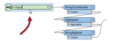
The first thing to know is that these input/output objects can be renamed, in order that the transformer ports get named appropriately. You can either double-click the object, choose Rename from the context menu, or press F2, in order to rename the object.
For example, here the user pressed F2 and renames the input port from StringConcatenator_Input to simply Input:
Adding or Removing Ports![]()
Besides renaming ports, it is also possible to add new ports to a custom transformer.
To do so simply select Transformer Input (or Output) from either the menubar or the canvas context (right-click) menu:


![]()
Post-Creation Parameter Handling![]()
As we know, custom transformers can be edited after creation.
The "Handle with Published Parameters" setting handles attributes used in a custom transformer only when it is created. There also needs to be a mechanism for handling future edits to a custom transformer (or where the custom transformer is simply created from scratch).
Handling Incoming Attributes
Attributes entering a custom transformer are handled using a setting inside the transformer definition.
As an example, an author puts a StringConcatenator inside a newly created custom transformer. The author wishes to concatenate AddressID and PostalCode.

AddressID is available in the custom transformer because it was being used when the custom transformer was created (and Handle With Published Parameters was set).
However, PostalCode is not available. It was not being used when the custom transformer was created.
Therefore the author must expose that attribute. They do so by inspecting the parameters for the Input port, where they are able to specify other incoming attributes to expose:

Now PostalCode becomes available to the StringConcatenator and, additionally, made into a user parameter so that back on the main canvas the custom transformer can accept a different attribute selection should PostalCode not be available.
Handling Outgoing Attributes
Besides incoming attributes, there is also the question of what attributes should emerge from the output of a custom transformer.
Best Practice suggests that we shouldn't output more attributes than are expected by the user. We should hide or remove any attributes that are part of a calculation, or any attributes that are otherwise generated inside the custom transformer but aren’t necessary to the output.
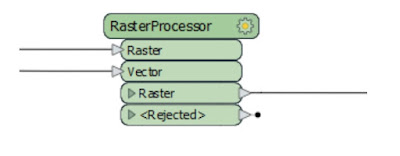
Here a custom transformer is calculating the average area of a number of polygon features. It has renamed ports and a specific output port to deal with bad features, but it is outputting more attributes than are useful:

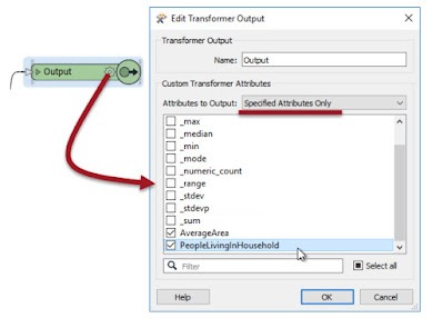
The Attributes to Output setting gives the option of outputting all attributes, or only those that have a checkmark next to them, as above.
Custom Transformers and Loops
A loop is a programming structure that allows an action to be implemented repeatedly. In most cases, a loop is linked to a condition; i.e., the action continues until a certain condition is met.
What is a Loop?
A loop is a programming structure that allows an action to be implemented repeatedly.
Often this is used to carry out iteration; where a process repeats to gradually narrow the process to the desired result. Usually, a loop is linked to a condition; i.e., the action continues until a certain condition is met.
In FME, loops are only permitted inside a custom transformer.
Loops and FME
In FME, loops are a way to repeat a section of transformers multiple times, without having to duplicate that section. For technical reasons, loops are only permitted inside a custom transformer.
As you know, FME processes one feature at a time. Therefore, when you create a loop, each feature is being sent around the loop individually.
So, to be worthwhile, each iteration of the loop must do something different. Often each iteration processes a different component of a feature (for example, reads records from a list) or repeats the same process using the results of the previous loop.
Setting up a Custom Transformer Loop
A loop in a custom transformer requires various components. The required components are:
- The start point of the loop
- The end point of the loop
Loop Start Points
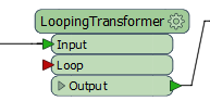
The start of the loop is identified by an Input port object. Although it can be the same input port as used for features to enter by, this does not have to be the case. For example here there is an input port for features to arrive into, and another one for the start of the loop:
This allows the loop point to be other than the beginning of the custom transformer.
By default, this second input port also appears on the transformer itself, like this:
If you don't require this, then you simply have to 'unpublish' it in the input port's parameters:

Loop End Points
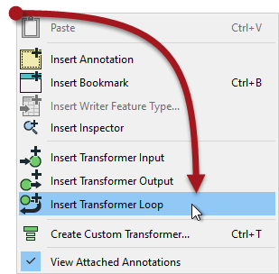
The end of a loop is identified by a Loop object. You can insert one by selecting it from the canvas context menu in a custom transformer:
When a loop object is placed you are asked which Input object it is to be looped to:

And then the loop is complete:

Of course, this example is an infinite loop. The action is repeated but there is no condition being tested to stop it. FME won't let an infinite loop run forever - it will recognize the problem and stop it - but we should set up something to force an ending.
Loop Conditions
There are two general types of condition we can test for. Firstly we can loop a set number of times. Secondly we can loop until a specific condition is met.
Here is a custom transformer that loops a set number of times:
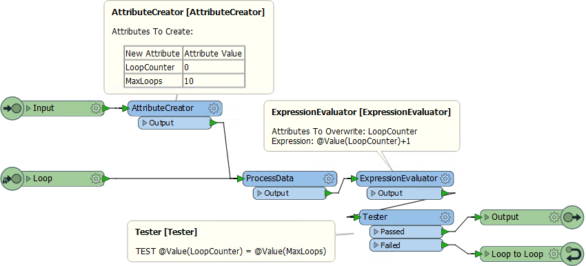
Notice that we have an attribute that is a counter for the number of times we have looped (LoopCounter), and an attribute that tells us the maximum number of loops to carry out (MaxLoops).
In each loop the counter attribute is incremented by 1. When LoopCounter < MaxLoops, then we loop back and process the data again. When LoopCounter = MaxLoops, then we exit the transformer.
Instead of a simple count of iterations, another method is to test a specific measure of data quality. For example, a polygon representing a political boundary is adjusted by moving vertices (the action), until the CircularityCalculator transformer returns a value of 0.5 or greater (the condition).
Loops and Transformer Types
As we are already know, transformers that operate on one feature at a time are called Feature-Based, and transformers that operate on multiple features at a time are called Group-Based.
We can also call a loop "Feature-Based" because it only processes one feature at a time. Unfortunately, that means that using a group-based transformer inside a (feature-based) custom transformer loop is not a simple task.
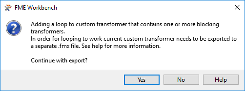
If you attempt to create a loop inside an embedded custom transformer, when it includes a group-based FME transformer, then you will receive an error message. Group-based transformers are only permitted inside a loop in a linked custom transformer. There are technical reasons for this that we won't go into right now.
This is the error message you will get:
So, inside a linked custom transformer definition, you'll see a particular parameter (in the Navigator window) called Enable Blocked Looping:

When set to Yes then other parameters are exposed to set the number of iterations and an attribute that will hold that value. Notice how parallel processing is turned off (the parameters are removed) for custom transformers that are being looped, and the Insert Mode is automatically changed to "Linked Only".
FME Feature Functions
One other item in the menu of both text and arithmetic editors is FME Feature Functions:

For example, the @Area() function returns the area of the current feature (assuming it is a polygon). @NumCoords() returns the number of vertices in the current feature.
Some functions return strings, and others return numeric values; therefore the available functions vary depending on whether the text or arithmetic editor is being used. In the screenshot above, the text editor functions are on the left and the arithmetic editor functions on the right.
FME Feature Functions are useful because they allow you to build processing directly into attribute creation, instead of using a separate transformer.
Replacing Other Transformers
Integrated text and arithmetic editors provide the benefit of multiple attribute-creating functions inside a single transformer.
For example, the AttributeManager Text Editor can be used as a direct replacement for the StringConcatenator and ExpressionEvaluator transformers.
The AttributeManager could also replace the StringPadder and AttributeTrimmer transformers, albeit with a little less user-friendliness. If FME Feature Functions are used inside the editor, this transformer could also technically replace transformers such as the AreaCalculator, LengthCalculator, VertexCounter, DateTimeStamper, and many more.
Integrating peripheral operations into a single transformer makes a workspace more compact and well-defined. However, best practice is critical to this setup. If an AttributeManager (for example) is not annotated correctly, it is incredibly difficult to determine what actions it is carrying out from the canvas alone!

Improving Reader Performance
The most important method to improve reading performance is to minimize the amount of data that is being read. As already mentioned, reading excess features counts as unnecessary work and is therefore inefficient.
Filtering Input
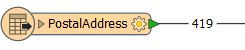
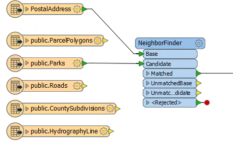
For example, this workspace reads nearly 14,000 features, but immediately discards all except 419 of them (ones where the owner's name begins with "C":
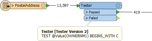
In this scenario, if possible, it would be much more efficient to simply just read those approximately 400 features. All formats have various sets of parameters that speed up feature reading by filtering the amount of data being read.
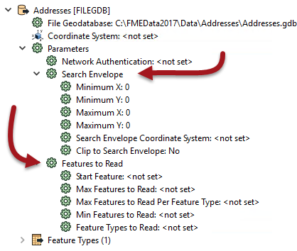
The first of these – search envelope – defines the data to read as a geographic area. Then only that area of data needs to be read. These parameters are available on every spatial data reader, but have the most effect when the source data is spatially indexed. Then the query is being carried out at its most efficient.
Similarly, there are a number of parameters designed to let the user define how many features to read. These parameters include the ability to define a maximum number of features to read, and what feature to start at. There is also a parameter that defines which feature types (layers or tables) should be read.
By using these judiciously, the amount of data being read can be reduced and the translation sped up. For example, if we knew that the first records in the dataset were the ones beginning with "C", we could set Max Features to Read to 419.
Other formats – particularly databases – have additional clauses that can help reduce the data flow:
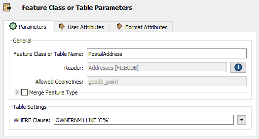
Here, for example, this Geodatabase reader has a ‘WHERE Clause’ parameter that applies the "owner name begins with 'C' test" in a way that is more efficient than reading the entire contents of a large table and using a Tester transformer.
Excess Feature Types
Another potential bottleneck - specifically for formats with a table list – is the case where you have more feature types than are necessary.
Here the user has added a number of tables to their PostGIS database reader:
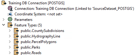
However, if you look at the workspace, many of these tables are not even connected to anything. The unconnected tables are still being read but the data is being ignored:
Presumably the user added the tables for some reason, but then decided they did not need them, In that case they should delete the feature type from the FME workspace. Then the table will not be read and performance will improve.
Remove Unattached
When developing a workspace, it is easy to lose Feature Types that are unused, especially once the workspace grows in size. To quickly remove these unused Feature Types go to Tools > Remove... > Remove Unattached in the menu bar.

Obviously this tool is less useful when there is just one unattached item, but is more useful in a larger workspace with an unknown number of unattached objects.
Improving Writer Performance
There are various ways to speed up writing data. Compared to reading, tuning the underlying systems is a more important improvement, whereas the number of features is less important as it's much harder to write extra data unintentionally.
Multiple Writers
Perhaps the most important technique for improving writer performance involves the scenario where a workspace has multiple writers.
In short, it’s important to get the writers into the optimum order, to ensure that the writer that is to receive the largest amount of data is written first.
The reasoning behind this is that the first writer in a workspace starts to write data as soon as it is received. Other writers cache theirs until they are ready to start writing.
Therefore, if the largest amount of data is written immediately, lesser amounts of data have to be written to, and stored in, a cache.
This can improve performance tremendously, particularly when the translation is especially unbalanced; for example one million features go to one writer, and only ten features go to another.
Setting Writer Order
There are two ways to affect the order that writing occurs in.
Firstly each writer is listed in the Navigator window in Workbench and can be re-ordered by moving them up and down in the list in the Navigator window:

The first writer in the list is the one that is executed first, therefore it should be the one to receive the most data.
The second method is to use a workspace parameter called Order Writers By:
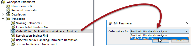
This parameter can be left to Position in Workbench Navigator in which case the order of writers as defined in the Navigator takes priority. Alternatively it can be set to First Feature Written. In that case the writer that receives the first feature will be the first to start writing data.
Improving Transformation Performance
The key to improving transformer performance is to reduce the amount of memory used, particularly in group-based transformers. To do this you can either reduce the amount of data entering a group-based transformer, or use parameters that, in the right conditions, can reduce the need to store data in memory.
Transformer Order and Filtering
Although the order of transformers can sometimes vary without affecting the result, at other times it is important to get the correct order for performance reasons.
You’ll get better performance when you put the least amount of data into a group-based transformer as possible. One scenario is to put feature-based filter transformers before the group-based process, not after it:
![]()
For example, here the author is filtering data after statistics have been calculated on one set of data. It would be more sensible to filter the data before calculating the statistics, otherwise processing has been carried out on features that were eventually ignored.
The best way to remember this is: Filter, Remove, Action!
In other words, filter first, then remove attributes, then carry out the action.
Group-By Mode Parameter
A common parameter to most Group-Based transformers is called "Group By Mode" and appears near the Group By parameter in most transformer dialogs:
![]()
When set to Process at End (Blocking) then ALL of the features are stored in memory until they are all available. Then groups are formed. The transformer is literally blocking data from proceeding.
When the parameter is set to Process When Group Changes (Advanced), then FME processes groups as they become available. That way less data is stored in memory and processing is more efficient.
The condition for applying this parameter is that the groups of features are pre-sorted into their groups.
For example, in the above screenshot, the user is using the ZoneCategory attribute as a group-by parameter (i.e. zones are dissolved together where they are the same category). If the incoming data is already sorted in order of ZoneCategory then the user can set the Group By Mode parameter and allow FME to process the data more efficiently.
Features First Parameter
Besides the "Group By Mode" parameter, some transformers have their own, unique, parameters for performance improvements. Many of these specify one type of feature to arrive "first."
For example, the PointOnAreaOverlayer transformer expects two sets of data: Points and Areas. By default, FME requires all incoming Points and Areas because it needs to be sure it has ALL of the Areas before it can process any Points.
But, if FME knows the Area features will arrive first (i.e. the first Point feature signifies the end of the Areas) then it doesn’t need all Point features. It can process each one immediately because it knows there are no more Areas that it could match against.
The user specifies that this is true using the parameter Areas First:
![]()
But how does a user ensure the Area features arrive first? Well, like writers you can change the order of readers in the Navigator so that the reader at the top of the list is read first.
Changing the reader order doesn’t improve performance per se, but it does let you apply performance-improving parameters like the above.
Attributes and Transformation
As mentioned (in Reader Performance) reducing data helps performance because it saves FME from either holding it in memory or caching it to a disk.
However, this isn’t just helped by reducing the number of features; it is also helped by reducing the size of each individual feature.
One aspect of this is attributes. Carrying attributes through a translation impacts performance, so if the attributes are not required in the output, it’s best to remove them as early as possible in the translation.
For example, when the reader and writer schemas look like this:
![]()
...it makes sense to remove excess attributes from the translation, as early as possible.
There are two ways to remove attributes. Some reader formats (but not all) have a setting in the reader feature type to avoid reading excess attributes in the first place:
![]()
With that, you can ensure that only attributes exposed are read. The other way to remove attributes is by using a transformer (AttributeManager, AttributeRemover, or AttributeKeeper) directly after the source feature type:
![]()
This ensures that none of the extra attributes become a drain on resources by being processed by any further transformers.
Geometry and Transformation
Like attributes, geometry can be removed from a feature, in this case using the GeometryRemover transformer.
Many FME users create translations that handle tabular – non-spatial – data. If you are reading a spatial dataset and writing it to a tabular format, be sure to remove the geometry early in the workspace, just as you would an attribute.
Another particular problem is carrying around spatial data as attributes. Spatial database formats - for example, Oracle or GeoMedia - usually store geometry within a field in the database; for example GEOM. When FME reads the data it converts the GEOM field into FME geometry and drops the field from the data.
However, if you read a geometry table with a non-geometry reader, the translation could end up with the geometry stored as an FME attribute. A similar thing could happen when a workspace reads only one geometry column of a multiple geometry tables.
Geometry will create very large and complex attributes, which take up a lot of resources. If you don’t need them, then it’s worth removing them.
Tolerance Parameters
FME introduces a tolerance parameter to many existing transformers, and one new transformer:
- AreaGapAndOverlapCleaner
- AreaOnAreaOverlayer
- Clipper
- Dissolver
- FeatureMerger
- Generalizer
- Intersector
- LineOnAreaOverlayer
- LineOnLineOverlayer
- Snapper
- Tiler
- TopologyBuilder
The AreaGapAndOverlapCleaner is, of course, the new transformer. It's a direct replacement for the SliverRemover. The Snapper already had a tolerance parameter, but that has been updated to use this new functionality.
So why these transformers? Because it's a set of transformers that use a common piece of code. That code was updated to allow a tolerance to be applied and was exposed as a new parameter:
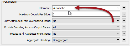
The tolerance parameters have three different options:
- None
- Automatic
- Custom Value
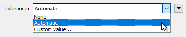
None means the transformer operates as it always did in FME; without any tolerance applied. The operation will be carried out using strict matches of coordinates. This is the default value (for 2018.0 at least).
Automatic means FME will decide upon a tolerance. Here FME is trying to resolve minor issues with coordinates, such as coordinate precision and rounding.
Custom Value means the user will enter a tolerance. The user is trying to resolve any issues they believe can be fixed through tolerance, such as bad geometry.
Collapsed Ports
Some transformers with the new tolerance setting have a Collapsed output port. This is for features whose size is smaller than the tolerance value, and which therefore collapse to a single point.
Example Geometry Problems
In general, data can not join, meet, or intersect because of one of two issues.
Firstly the geometry of the data can have simply been created badly:
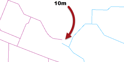
In that example the two lines are meant to connect, but instead have a gap of around 10 metres.
The second source of problems is geometry that has very tiny imperfections due to issues such as coordinate rounding:
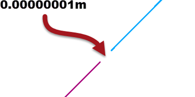
In this case the two lines are meant to connect, but instead there is a very small gap of 0.00000001 metres. This sort of error is very difficult to locate visually, because of its small size.
Such an issue might arise because of coordinate rounding (coordinates are rounded to a precision that leads to gaps), because of different data formats (where each format stores coordinates in slightly different ways), or perhaps because of some other automated process that has been carried out.
No Tolerance
When tolerance is set to none, then the above features are not considered a match.
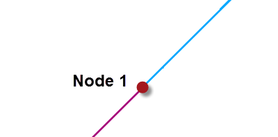
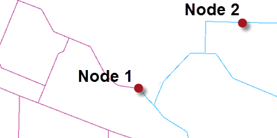
For example, in a TopologyBuilder, the gaps in each case would lead FME to assume that each geometry is a road that ends without a connection. There would be two nodes with a gap between them:
Depending on the data this may or may not be the correct result. With a gap of only 0.00000001 metres we can safely assume it is not correct in this example.
Automatic Tolerance
When tolerance is set to automatic, then FME will assess the data and come up with a reasonable tolerance to solve minor problems. For example, in a TopologyBuilder FME would correctly determine that the smaller gap is an error that should be corrected:
However, it will not fix the grosser error that caused the larger tolerance gap:
That's because there is no way FME could reasonably define that as a problem, or fix it without possibly altering other similar gaps.
Custom Tolerance
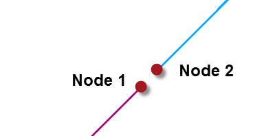
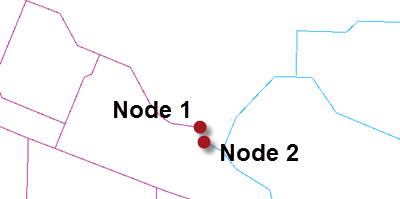
When the tolerance is set to a custom value then the author is trying to resolve issues at a scale of their own choosing. For example, in the TopologyBuilder they could set a tolerance of 10. That would solve both the small issues and the larger one:
But it might also mistakenly fix issues where two points are legitimately within 10 metres of each other, like at Node 2.
So in general cases it's best to use automatic tolerance, unless you can be sure that a custom tolerance will work as you want it to.
Saving Cached Data
Because workspaces can be worked on over several sessions, and because you might want to transfer a workspace with caches to another user, saving a workspace as a template also gives the option to save the data caches:
That way any workspace created from the template automatically gains access to the caches from the previous run.


No comments:
Post a Comment