

Coordinate System Transformation
A coordinate system is a reference system for spatial data to be related to a particular space on the Earth's surface.
A coordinate system includes projection, datum, ellipsoid, units, and sometimes a quadrant.

Each Coordinate System parameter is linked to FME's Coordinate System Gallery. Double-click the parameter to display a list of recently used coordinate systems, or More Coord Systems to access FME's
Like the source schema, the reader coordinate system is "what we have" and the writer coordinate system is "what we want".
Automatic Detection of Coordinate Systems
It's not always necessary to set the coordinate system parameters manually. Some data formats (for example Esri Shapefile) are capable of storing information about the coordinate system in which they are held, and FME will retrieve this information where it can.


Here, because the reader coordinate system is marked <not set>, FME will try to determine the coordinate system from the source dataset. If it can't, then the feature will be tagged with a coordinate system of <unknown>.
There are a number of reprojection scenarios that may occur depending on the combination of coordinate system (CS) information available. Here N means "not set" and S means "set":
Dataset CS | Reader CS | Writer CS | Reprojection |
N | S | S | Reprojects from Reader CS to Writer CS |
S | N | S | Reprojects from Dataset CS to Writer CS |
N | N | S | Error: Cannot reproject without Dataset or Reader CS |
S | S | S | Reprojects from Reader CS to Writer CS |
S | S | N | No reprojection unless the format requires it |
If the coordinate system is not set on the writer, then no reprojection will take place unless the output format requires it. For example, the KML format requires data to be in Latitude/Longitude. If neither the source dataset or the reader coordinate system is defined, then the translation will fail.
How FME Processes Coordinate Systems in the Workspace
-> If a coordinate system is specified in both the source format and the workspace, the coordinate system in the workspace is used. The coordinate system specified in the source format is not used, and a warning is logged.
-> If a source coordinate system is not specified in the workspace and the format or system does not store coordinate system information, then the coordinate system is not set for the features that are read.
->If a destination coordinate system is set and the feature has been tagged with a coordinate system, then a coordinate system conversion is performed to put the feature into the destination system. This happens right before the feature enters into the destination writer.
-> If the destination coordinate system was not set, then the features are written out in their original coordinate system.
->If a destination coordinate system is set, but the source coordinate system was not specified in the workspace or stored in the source format, then no conversion is performed. The features are simply tagged with the output system name before being written to the output dataset.
Reprojecting Data
By default, FME chooses a coordinate system for destination data sets according to the rules specified in How FME Processes Coordinate Systems in the Workspace. Alternatively, you can direct FME to reproject data to a destination coordinate system that you specify.
To specify a reprojection, do one of the following:
- In the Workbench Navigator, specify the writer coordinate system.
- Use a transformer that reprojects features to a specified coordinate system.
Note: The Reprojector transformer does not provide the option of specifying a datum, and is considered an "implicit" conversion.
When choosing between implicit and explicit reprojection, keep in mind the following:
- Using a transformer to reproject data is necessary when working with multiple datasets that have different coordinate systems, and your workspace requires that their features interact geographically before they are written out. This is because in implicit conversion, reprojection does not occur until just before features are written out.
- Using explicit reprojection with data formats that specify coordinate systems in feature attributes may lead to unexpected results. Using implicit reprojection is recommended in these cases.
- When using implicit reprojection, the datum transformation that is selected by default may change between product releases.
FME has several reprojector transformers, using different reprojection engines:
- CsmapReprojector uses the CS-MAP reprojection engine to do horizontal and vertical transformations. CS-MAP is a general reprojection engine that is included with FME and includes definitions for thousands of coordinate systems, with a large variety of projections, datums, ellipsoids and units. CS-MAP is also used by Autodesk applications.
- Reprojector is a simpler version of the CsmapReprojector for horizontal reprojection only. It does not allow you to choose a datum transformation, or override the source data coordinate system.
- ESRIReprojector uses the ArcGIS reprojection engine. ArcGIS must be installed and licensed on the same computer as FME for this transformer to work. It uses the ArcGIS reprojection interface to choose both the coordinate systems and datum transformations, and supports user created coordinate systems and datums transformations.
- GridInQuestReprojector uses the GridInQuest reprojection engine to perform horizontal and vertical transformations within the United Kingdom and Ireland.
- GTransReprojector uses the GTrans reprojection engine to perform coordinate system conversion in the Scandinavian region.
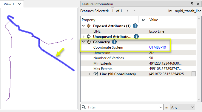
In this example, we have a shapefile of transit lines. Note that the FME Data Inspector knows what the coordinate system is and displays it, but that information is not readily accessible in attribute form.
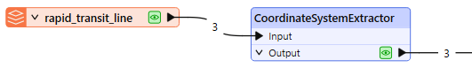
The transit lines are routed into a CoordinateSystemExtractor.
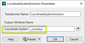
In the parameters dialog, we keep the default Coordinate System Attribute name of _coordsys.
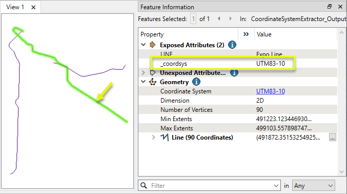
The output features now have the coordinate system name stored as a new attribute.
- The FME representation of a coordinate system can be extracted into an attribute with a CoordinateSystemExtractor.
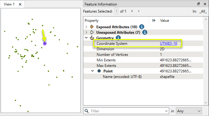
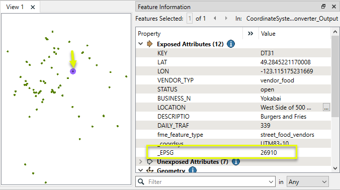
In this example, we want to retrieve the EPSG number associated with the coordinate system of a shapefile of food vendors.
Note that while the coordinate system is known (UTM83-10), it is not accessible as an attribute.
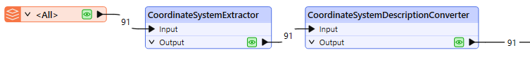
The features are routed first into a CoordinateSystemExtractor, and then on to a CoordinateSystemDescriptionConverter.
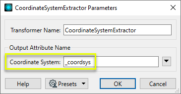
In the parameters dialog of the CoordinateSystemExtractor, the default name for the new attribute to contain the coordinate system information is _coordsys.
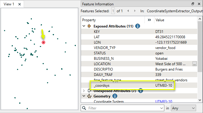
Using the FME Data Inspector to examine the features as they exit the transformer, we can see that the FME representation of the coordinate system - UTM83-10 - has been added to the new _coordsys attribute.
In the parameters dialog of the CoordinateSystemDescriptionConverter, we identify the new _coordsys attribute, choose Convert From FME Representation, select EPSG Number as the destination representation, and edit the new attribute name which will hold the results.
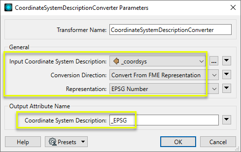
The output features have a new attribute, _EPSG, containing the EPSG number.
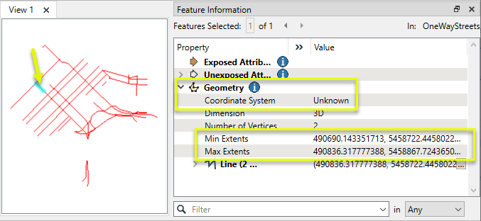
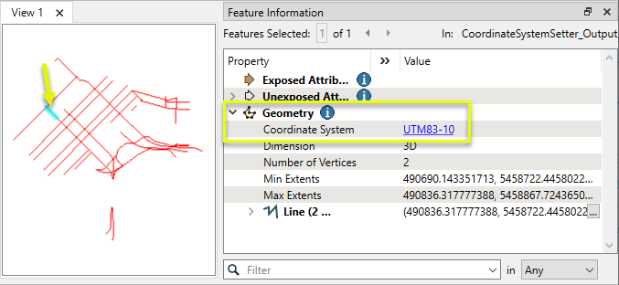
In this example, we have a DWG (CAD) file of one-way streets. Though DWG files can come with coordinate system information attached, this one does not have it. Note that the extents of the selected feature would be appropriate coordinates for a UTM coordinate system.
We do know that the data is in UTM83-10, and need to assign that coordinate system to the data without modifying the feature geometry.
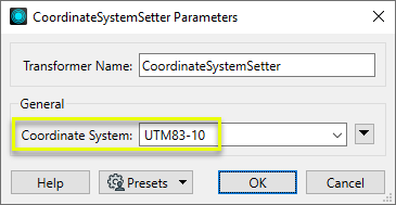
The features are routed into a CoordinateSystemSetter.

In the parameters dialog, Coordinate System is set to UTM83-10.
The output features now know their coordinate system, and the coordinates themselves have not been modified.
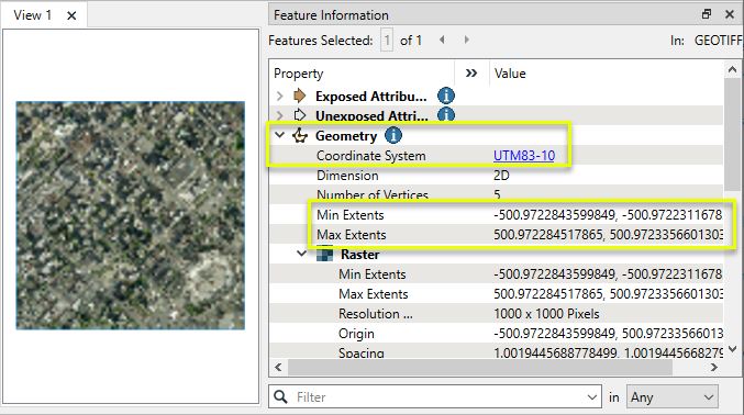
In this example, we have a raster that appears to be in a local coordinate system but has an assigned coordinate system of UTM83-10.
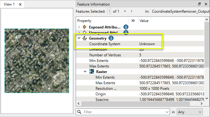
The raster is routed into a CoordinateSystemRemover, which has no parameters to set.
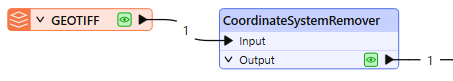
The output feature has its coordinate system removed, but its coordinates are unchanged.
- A coordinate system can be replaced without altering the geometry or coordinates by using a CoordinateSystemSetter.
- Possession of a coordinate system definition doesn’t control whether writers create coordinate system-related metadata such as wld or prj files. These are controlled by writer parameters
In this example, we start with a CSV file of drinking fountain locations. A CSV dataset has no geometry, but it does contain coordinates for the fountains, in a UTM projection.
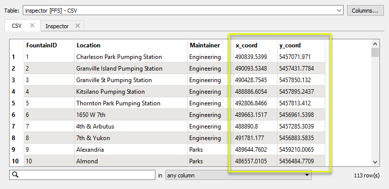
The CSV features are routed into an AttributeReprojector.
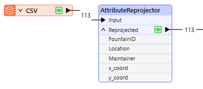
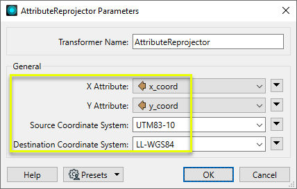
In the parameters dialog, the x and y attributes containing the coordinates are specified accordingly, the source coordinate system entered (as UTM83-10), and the new destination coordinate system chosen (LL-WGS84).
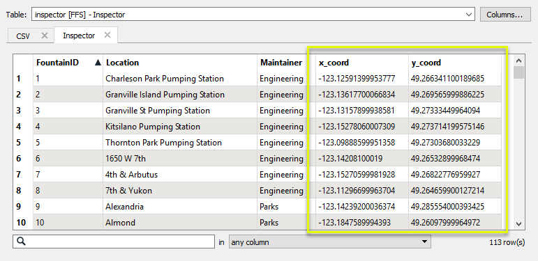
The new coordinates are calculated and replace the existing attribute values. The transformer does not create geometry, it only supplies values.
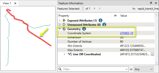
In this example, we have a shapefile of transit lines, projected in the coordinate system UTM83-10 - UTM Zone 10, NAD83 (North American Datum 1983).
We want to reproject them into an older datum - NAD27.
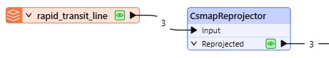
The features are routed into a CsmapReprojector.
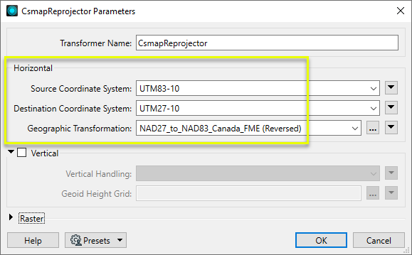
In the parameters dialog, both the Source and Destination Coordinate Systems are explicitly defined.
Though we could leave the Source Coordinate System as <Read from feature>, explicitly defining both of them gives us access to the available Transformations for that combination of coordinate systems. There are two, and we select the Canadian one for this dataset. Note that the direction is Reversed since we are going from the newer datum to the older one.
If we had previously set a preference in FME Options > Coordinate Systems > Implicit Transformations to either Canada Only or USA Only, the <Auto> Transformation option would use that setting.
The data is 2D, so Vertical Handling is left as Ignore heights and leave them unchanged.
The output features are reprojected to UTM27-10.
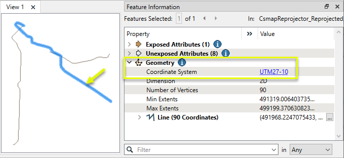
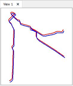
Examining both the input (red) and output (blue) features overlaid in the FME Data Inspector (with the Background Map OFF), we can see the results of the datum shift, based on the Canadian NTv2 grid shift file.
Transformer Name:- Reprojector
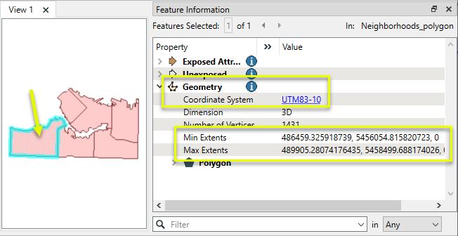
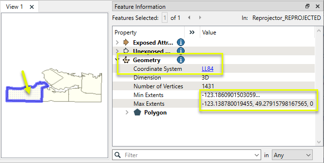
In this example, we have a set of neighborhood polygons. Note that the coordinate system is known, UTM83-10, and the extents are provided in meters.
We want to reproject them to geographic coordinates, latitude and longitude, WGS84.
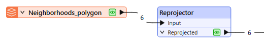
The features are routed into a Reprojector.
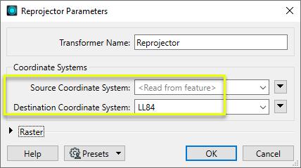
In the parameters dialog, we leave Source Coordinate System as its default, Read from feature. The Destination Coordinate System is set to LL84.
The output features have been reprojected.
Usage Notes
- Reprojector does not alter z values. For handling elevation or vertical coordinate systems, consider using a CsmapReprojector.
- For finer control, including Geographic Transformation selections, consider using a CsmapReprojector or EsriReprojector.
- Reprojector & CsmapReprojector operates on features with geometry. To reproject coordinates stored as attributes, see the AttributeReprojectoror or CsmapAttributeReprojector.
- Create a workspace, and define your reader and writer.
- In the source dataset area in the Navigator pane, the Coordinate System parameter will be displayed as <not set>. This means that FME will either use default values, or will read the coordinate system from the source data.

You can explicitly set the source coordinate system (which will override any coordinate system read from the source) but in most cases, you will not need to change the default parameter.
- In the destination dataset area of the Navigator pane, double-click the Coordinate System parameter.
- In the dialog that appears, you can either click the Browse button to display the Coordinate System Gallery or enter a prefix or character string that will display a list of matching selections. For example, if you type the string "UTM" you will see these matches:

- FME will reproject the data to the coordinate system that you enter in this field, and the Navigator pane will display something similar to this:

These transformers perform various coordinate system-related tasks, but do not reproject the data.
Looks up coordinate system names and definitions between FME’s internal format and common third-party and open source representations, storing the results as an attribute. | |
Retrieves the name of the feature's assigned FME coordinate system into an attribute. | |
Removes the coordinate system from features, without modifying geometry or coordinates. | |
Assigns a specified coordinate system to features, without modifying geometry or coordinates. | |
Assigns a specified local coordinate system to features, without modifying geometry or coordinates. |
Transformer Name | Description | Library |
Reprojects x and y coordinates stored as attributes from one coordinate system to another. | FME (default) or Esri | |
Reprojects one or more features to a local coordinate system centered on the bounding box containing all features. | FME (default) or Esri | |
Converts a given angle from one coordinate system to another. | FME (default) or Esri | |
Converts a given length from one coordinate system to another. | FME (default) or Esri | |
Reprojects feature x and y coordinates from one coordinate system to another. | FME (default) or Esri |
Transformer Name | Description | Library |
Reprojects x, y, and optionally z coordinates stored as attributes from one coordinate system to another using the CS-MAP library. | ||
Reprojects feature x, y, and optionally z coordinates from one coordinate system to another using the CS-Map library. | ||
Reprojects feature coordinates from one coordinate system to another using the Esri reprojection library. | ||
Great Britain Northern Ireland Republic of Ireland | Reprojects feature coordinates from one coordinate system to another using the Grid InQuestII engine from Ordnance Survey, for use in Great Britain, Ireland, and Northern Ireland. | |
Sweden | Reprojects coordinates stored as attributes from one coordinate system to another using the Gtrans reprojection engine from the National Land Survey of Sweden (Lantmäteriet). | |
Sweden | Reprojects feature coordinates from one coordinate system to another using the Gtrans reprojection engine from the National Land Survey of Sweden (Lantmäteriet). | |
Reprojects coordinates stored as attributes from one coordinate system to another using the PROJ library. | ||
Reprojects feature coordinates from one coordinate system to another using the PROJ library. | ||
Switzerland | Reprojects feature coordinates from one coordinate system to another in Switzerland, using the Reframe library from the Federal Office of Topography (swisstopo). |


No comments:
Post a Comment